Archive for the ‘Uncategorized’ Category

Final Report
december 19, 2008

This is the report we turned in for our 7´th semester 2009 examination at Architecture & Design. The report illustrates our process, theories and the final product. The project has been very educational and brought a high level of insight in dealing with parametic software and way of thought in a design process.

living-bridgead7ark120081

Regards

Mathias and Christian

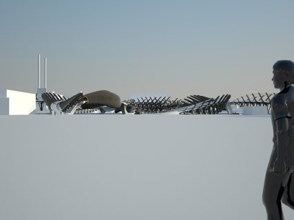
First image of the entire bridge in context
december 14, 2008


Image taken from the Nørresunby side, looking towards Aalborg with the “Teknisk Forvaltning” on the right.stigsborgbrygge

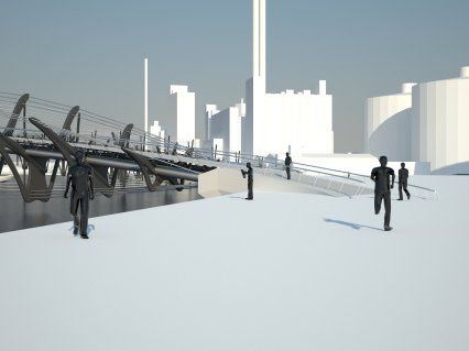
Image showing the landing of the bridge in front of the soon to be “Musikkens hus” designed by Coop Himmelblau and the “Østre Havn” in the background.  fra_musikhus_1c2bd

First glimpse of joined parametric parts
december 11, 2008

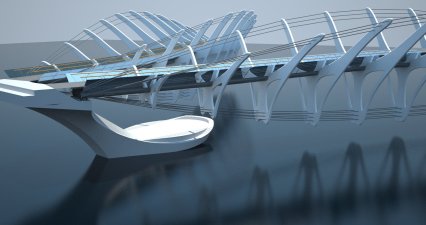
first-glimpseNow the final parametric models for both the concrete bridge pillars and the sections found from staad pro are put together with the model of the bridge deck and construction. The pillars have stairs leading down to the platform below, were seating and access to the water is found. The platform acts as a counterweight to balance the non-vertical pillar.

Acoustic Clarity Analysis Tool
december 11, 2008

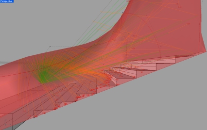
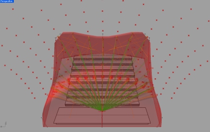
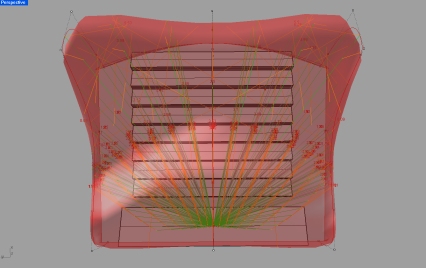
The need to incorporate an auditorium to our living bridge brought up the subject of designing according to acoustic rules to create an appropriate space. Therefor we saw that one of the most valuable tools in determining geometry for acoustic spaces was “acoustic clarity”. We therefor developed a tool in grasshopper to calculate the  reflection of  lines comming from a central point on stage and then calculate the whether or not the difference between the relfection rays to any given point is less than 7 m a part from the direct line to the source.clarity_1The next image shows the points the green lines are shooting for which is evenlys distributed points on a surface.

clarity_2

clarity_3

More details added to parametric model
december 8, 2008

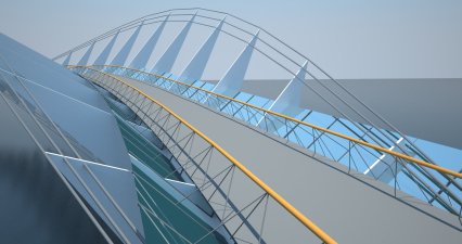
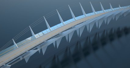
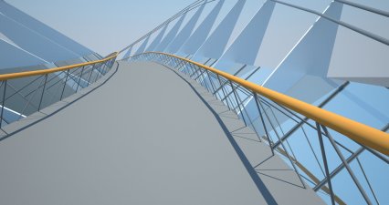
The parametric model has been expanded to contain the discription of other details of the bridge segment, like the bridge deck, the handrail and its supports and a glass wind shield with supports. The supporting pressurized pipes are also included. All pipe sizes and the placement and shape of handrail and glass can be changed freely as well as the number of supports. All geometry shown in these pictures are drawn in the parametric model. The pointy sections are not correct, but the approximation materialer-parametrisk21materialer-parametrisk1

materialer-parametrisk31

Plan
december 4, 2008

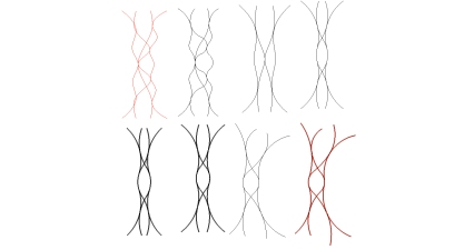
Here is a few pictures from the ongoing developement of the plan. All parts of the bridge consists of arch segments, that can be used to define the individual bridge parts.

sketching process. From top left to buttom right.

sketching process. From top left to buttom right.Topview of bridge with the first attempt to apply bridge parts from the parametric model. The bridge lands in front of the coming Musikkens Hus (concert hall)A first glimpse of the visual impact.


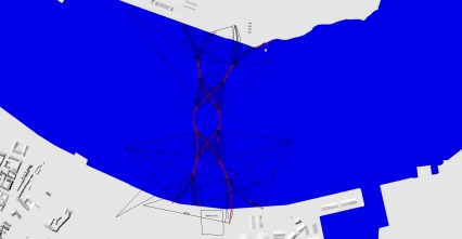
Topview of the plan.

Topview of the plan.

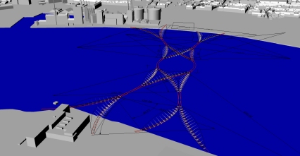
A first glimpse of the visual impact on the site.

A first glimpse of the visual impact on the site.

Parametric model with embedded force analysis
december 4, 2008

Finally the parametric model is up and running. All forces working on each section are mathematically defined as a result of geometry, size and local cable forces and represented by a z and a xy vector. The moment is not considered, since any rotational deformation will happen around the central axis if the resulting z and xy forces are in equilibrium.

the bridge sections are mounted on two pipes (not drawn in the model) running in longitudinal direction. The area centroid of their sections is the center of rotation represented by a dot in the center of the moment. These pipes are thought to be stiff enough to take smaller loads in different directions. This is important, becouse equilibrium of the structure is reached manually, and it is impossible to reach perfect equilibrium from manipulating the cables and forces, and because the model is only an approximation. Forces of around 1ton is guessed to be acceptable, as long as the deviation is distributed in different directions along the bridge, and thus not working in the same direction accumulating greater forces.

A list of all acting forces can be received from the program as well, but the maximum cable forces are at the bridge ends, where they are defined.

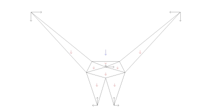
This is a map of the resultig forces acting on each section as defined in the program. The black vectors represent the cable forces at the tips and the resulting forces from the curved pressurized pipes in the center. The blue vector represents the weight of bridge deck, cables and pipes and the red vectors represent the weights of the different parts af the section.

This is a map of the resultig forces acting on each section as defined in the program. The black vectors represent the cable forces at the tips and the resulting forces from the curved pressurized pipes in the center. The blue vector represents the weight of bridge deck, cables and pipes and the red vectors represent the weights of the different parts af the section.

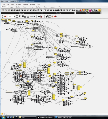
We had to show this... The complex structure avaluates all forces and geometry. The geometry/densities/cable forces can be manipulated from more than 20 number sliders.

We had to show this... The complex structure avaluates all forces and geometry. The geometry/densities/cable forces can be manipulated from more than 20 number sliders.

The output of the program is goemtry and the resulting forces represented by two points. One showing the vertical, one showing the horizontal force vector. The length of the vector, the distance between the point and the center of the plane shown, is equal to the resulting force in 10kN (appr. 1 ton). The goal is to maniplate the geometry and the forces to get both the horizontal and the vertical points of all sections within one meter from the cenerpoint.

The output of the program is goemtry and the resulting forces represented by two points. One showing the vertical, one showing the horizontal force vector. The length of the vector, the distance between the point and the center of the plane shown, is equal to the resulting force in 10kN (appr. 1 ton). The goal is to maniplate the geometry and the forces to get both the horizontal and the vertical points of all sections within one meter from the cenerpoint.

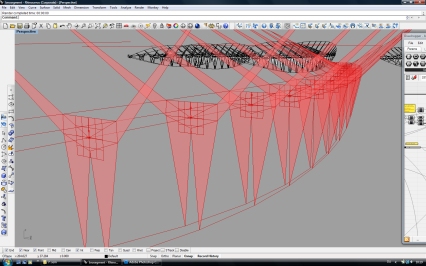
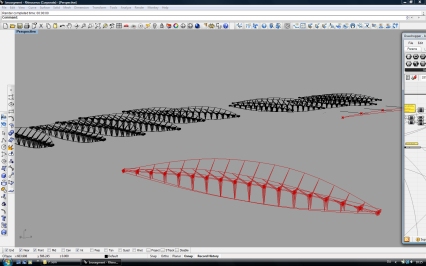
Each bridge elemnt can be shaped by the program and "baked" to become "real" drawings. This picture shows the parametric model and a number of bridge elements drawn from it.

Each bridge elemnt can be shaped by the program and

Sandwich Skin Construction
december 3, 2008

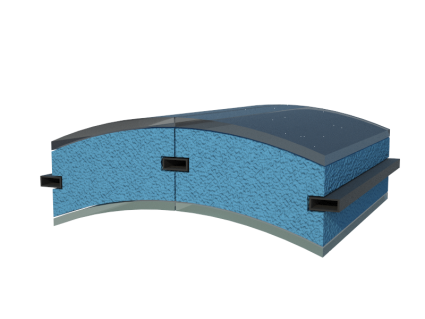
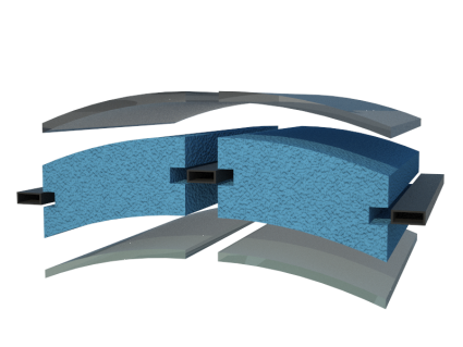
We want the skin of the bridge spaces to be smooth, and we want to be able to control transparence freely. The skin also has to be lightweigt and to have insulating properties.

The solution is a sandwich shell consisting of a dense foam core with cut holes for light and two transparent polyarbonate plates. The foam cores are fixed bysteel trusses running horizontally perpendicular to, and fixed to, the large steel ribs. This allows us to have a skin, that can be perforatet almost freely without the “cold bridges” that would otherwise occur, and at the same time perform okay as insulation for an outdoor stage. The steel ribs will either show on the inside or the outside of the shell. At the moment we want them to be on the outside.

sandwich_konstruktion_2sandwich_konstruktion_3

Transparency with circular patterns
december 3, 2008

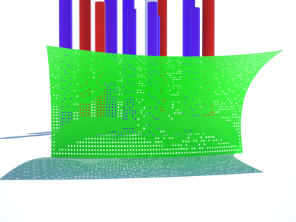
We would like to create transparency inside the spaces we create but we don´t want a regular window we would like to diffuse the boudary between the ind´side and the outside. This is currently being tested by using circular patterns that penetrate the outerskin and gives way for the view. There will be an ongoing testing on the size, the amount and the internal distances, to create the right transparency and feel. The image below illustrates the current idea.

cirkel_huller_1

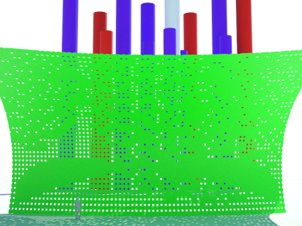
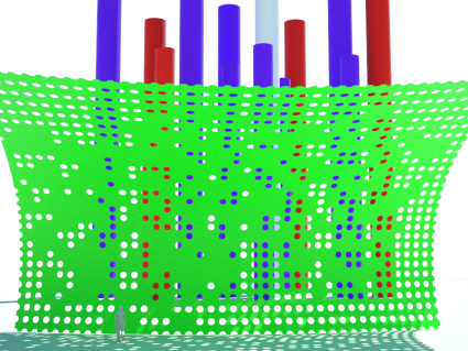
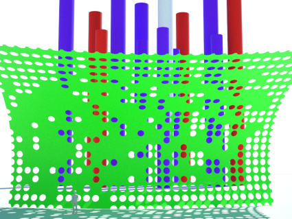
The next three images are illustrating three different settings for the diameter of the cicular holes, viewed from a distance of 20 meters.

First, Diameter 20 cm, distance from next circle 20 cm.

cirkel_huller_2_radius_01m_20-meter_vc3a6kSecond, Diameter 40 cm, distance from next circle 25 cm.cirkel_huller_2_radius_02m_20-meter_vc3a6k

Third, Diameter 60 cm, distance from next circle 20 cm.cirkel_huller_2_radius_03m_20-meter_vc3a6k

Outdoor Stage
december 2, 2008

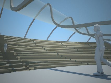
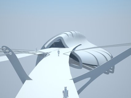
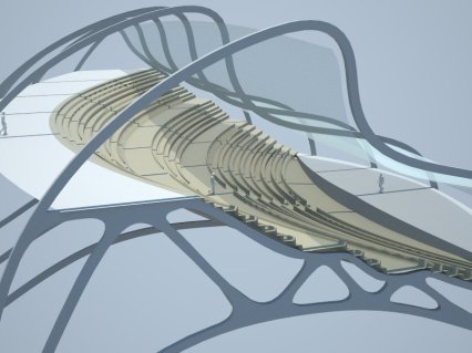
The hopeful Musikkenshus needs an outdoor stage to go along with the indoor one, we have decided to implement this in our bridge, since this could benefit the life on the bridge at late hours of the day. Therby giving room for a living bridge functioning most the day, for something else than just transport.

To accompany the lightweight structure with a grand scale stage it is nessesary to look at optimizing the suspended structure while maintaining structural efficency of the cable structure. This optimization is ongoing and the pictures below shows the current stage of the design.
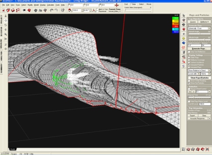
489While it has been very important to use to integrate the Oudoor Stage to aesthetics and structure of the cable structure, it is also a important to look at accustic calculations to judge the overall design. To meet this need we have teamed up with Ecotect´s accustics calculator. Using this we have entered the 3d model and applied a central sound source, applied material data to surfaces and entered number of seatings and what the seats are composed of. To evaluate the design we have been lokking at the distribution of the particles being emmited from the sound source, seen in the three images below.
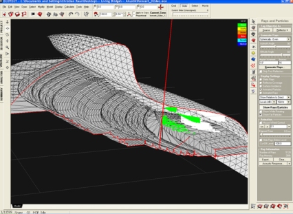
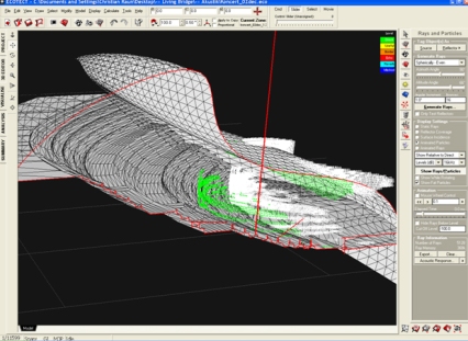
ecotect_2dec_4ecotect_2dec_3ecotect_2dec_2

The particles show a good distribution throughout the seating area with very much direct sound being obtained even at the backrows. The curved roof gives possibility to have good reflections of the sound but it also creates somewhat of an echo for the stage area which in this case will need very absorbant material not yet applied to the design.

The reverbration times are displayed in the next image.
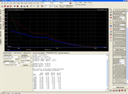
ecotect_2dec_1Further optimizations of the structure is needed, both in the materials and the possible retractable roof or other opening mechanisms.